In a sentence, Project Y is my attempt at characterizing the acoustic field generated by a supersonic flow. I designed and developed an electromechanical system to rotate a diamond-shaped nozzle while simultaneously exhausting supersonic flow at Mach 2 and collecting data. Initially, the tests will collect acoustic data while the jet is "cold". After that, I'll move on to visualizing the flow using a technique known as PIV(Particle Image Velocimetry). Finally, the upstream air supply will go through a combustion process until it reaches 1700°F(~930 °C) and I can collect heated jet noise and flow visualization to characterize the features of this unique nozzle geometry.
What is Project Y?
How it started
I was introduced to jet acoustics when I started graduate school. I had gotten to explore the Anechoic Hot Jet facility at the FAMU-FSU College of Engineering and sampled some experiments using a tradiational round nozzle. When I was introduced to this diamond nozzle, I went through the same type of tests. I placed it in the anechoic facility, fired it up, and recorded the noise in two configurations. The first, where the longer (major) axis of the nozzle was in-line with the far-field microphone array. Then I would rotate the nozzle 90° and record noise when the other axis was on the same plane as the mics.
Since my academic career was going to be based on this, non-axisymmetric, diamond shaped supersonic nozzle; I realized that recording the noise and visualizing flow from these 2 perspectives wasn't quite enough. Hence, Project Y was born. I was discussing research goals and how I wanted to rotate the nozzle and peak at the flow/acoustics from a ton of different perspectives when Dr. Fernando Zigunov (Scholar) mentioned that rather than reset the experiment everytime I wanted to rotate the nozzle, I could automate the process. The first thing we did was discuss how we could make this mechanism without forcing a rigorous redesign of a facility that works ,for the most part, just fine.
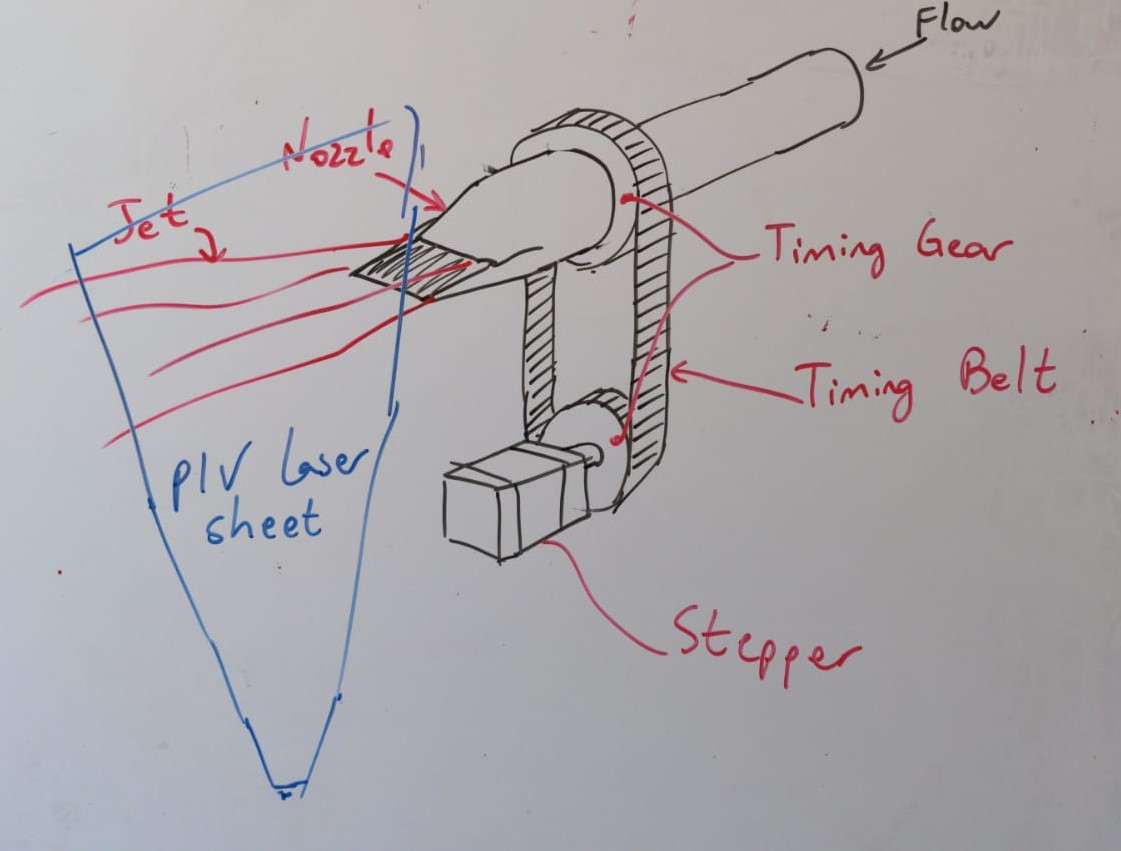
Whiteboard development of the concept of nozzle rotation and how to implement it without redesigning the entire hotjet facility.
Mock-ups
Soon after that, I went straight to a CAD platform and started mocking up my rotation mechanism. This helped me figure how I wanted to move forward, but mostly, I hadn't used CAD software in a couple of years and this served as a fantastic refresher course. I started simple, I had two sprockets that were the exact same size at some set distance from each other. My initial goal was to assemble them using a chain. After a couple of attempts, I got a better hand on how to use CAD and had a neat animation to show off.
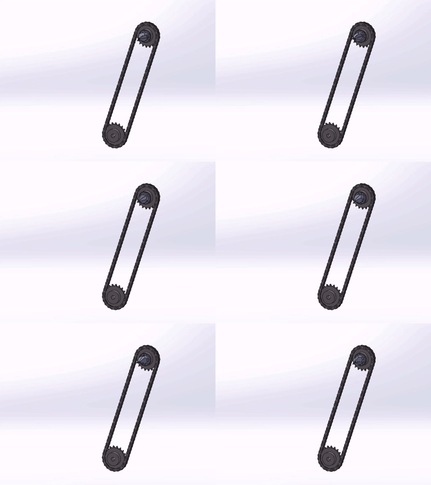
A CAD exercise to assemble mechanical components and create a functional animation of the components working together to illustrate the mechanism that will drive the project.
Now it was time for the real deal. I wanted to use hardware that, for the most part, could be found on a major supply company's website (McMaster-Carr). I scoured their site looking at a variety of sprockets, shafts, chains, and tensioners. I downloaded a couple of the CAD files available and would build it together. After a few iterations, I found the sprocket/chain size that was "just right" for my purpose and started to make a more rigorous assembly. My peer Serdar Seckin (Scholar) played a significant role while I was developing my setup and bringing it all together. When all was said and done, only two parts of the assembly had to be made from scratch in a machine shop which kept costs down. The plans were ready and it was almost time for assembly. Below are a pair of images illustrating the full assembly design before purchasing any products
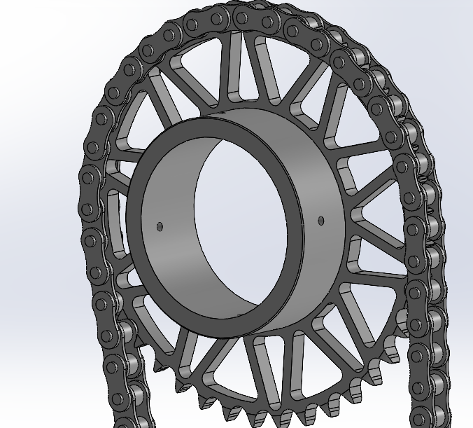
Top half of complete CAD design. Online/interactive CAD drawing below.
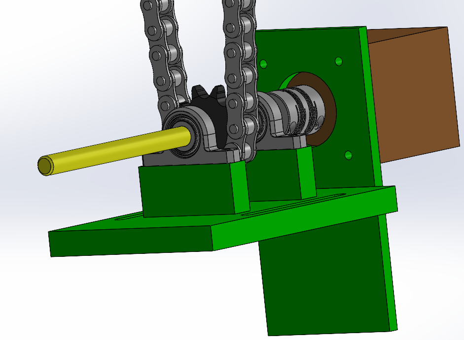
Bottom half of complete CAD design. Online/interactive CAD drawing below.
Full-scale assembly and testing
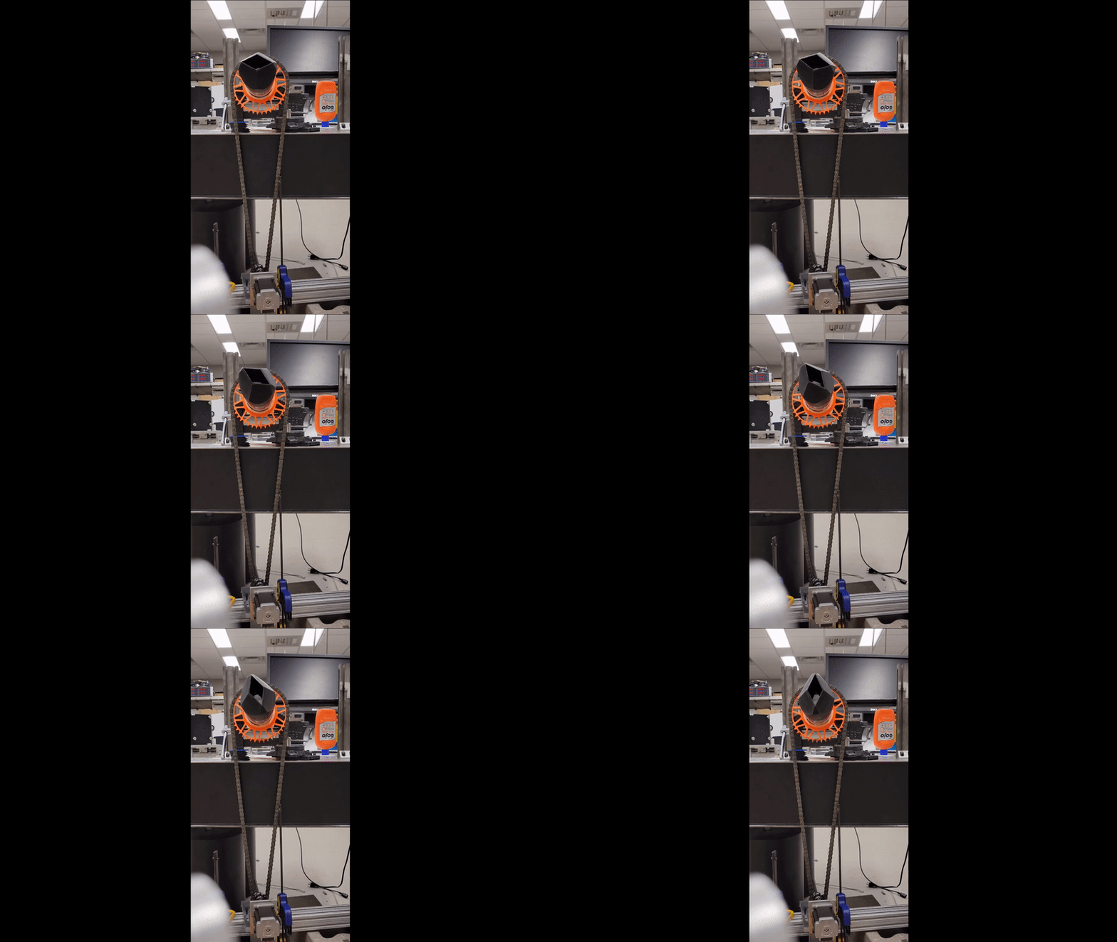
A gif of the full-scale test bench view.
Trouble in Paradise
Soon after that, I installed it in the anechoic chamber and put everything together. It was working! I spent the next few days playing around with the data acquisition & control code, spinning the nozzle from my computer, and doing a couple of dry tests. Finally, I was ready to try and run a full scale test. This is where I realized my first mistake.
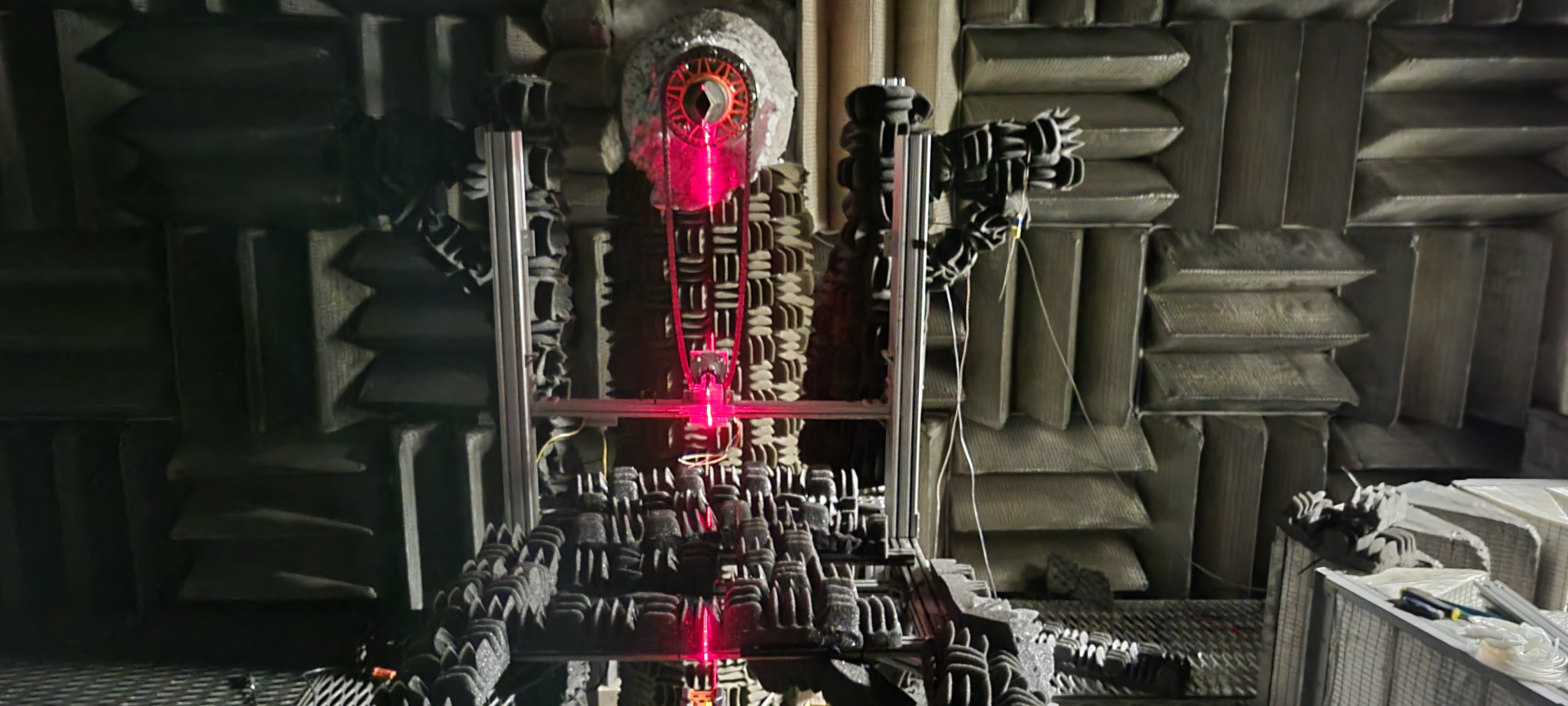
An image of the Project Y assembly in the anechoic chamber.
My design had been working wonderfully during all of my dry runs, but the nozzle just would not rotate when I sent a command during testing! After some troubleshooting, I eventually figured out that even with my gear reduction, my motor could not generate enough torque to rotate the nozzle under load. "Well...now what?" I thought to myself. After a few minutes of panicking, I realized two things. The first, was that I could still build a three dimensional acoustic profile around my nozzle. The only caveat was that we would need to cycle through shutting down and starting up flow in the facility every time I wanted to rotate the nozzle; but hey, I could capture data and try to make my pretty acoustic surface plots.
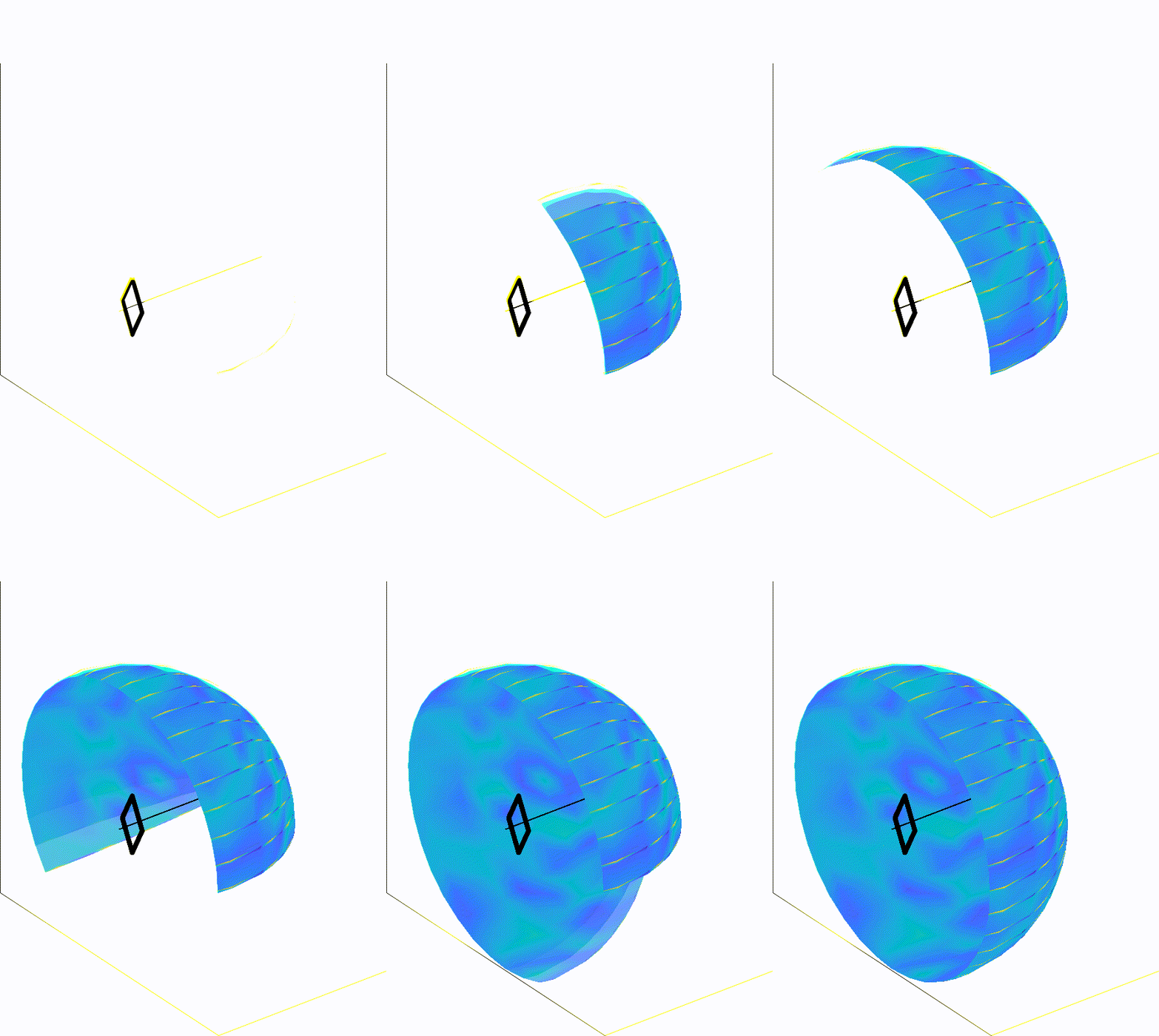
Animation illustrating the development of a far-field accoustic surface.
Next, I figured that all I needed was a quick redesign! But first I would need to calculate how much torque I actually needed to rotate the nozzle once there was air flowing. Some internet browsing led me to the conclusion that trying to rotate a screw under load is not common practice in the world of engineering. I'd have to use some other model to estimate how much torque it takes to rotate my nozzle. I found three different resources on techniques I could use. The situation that most realistically matched my situation, was calculating the torque required to overcome static friction on a disc under load. From here, I could come up with a torque to design for. The solution seemed to be another torque multiplier. This time I was going to use a worm and its accompanying worm gear to increase torque.
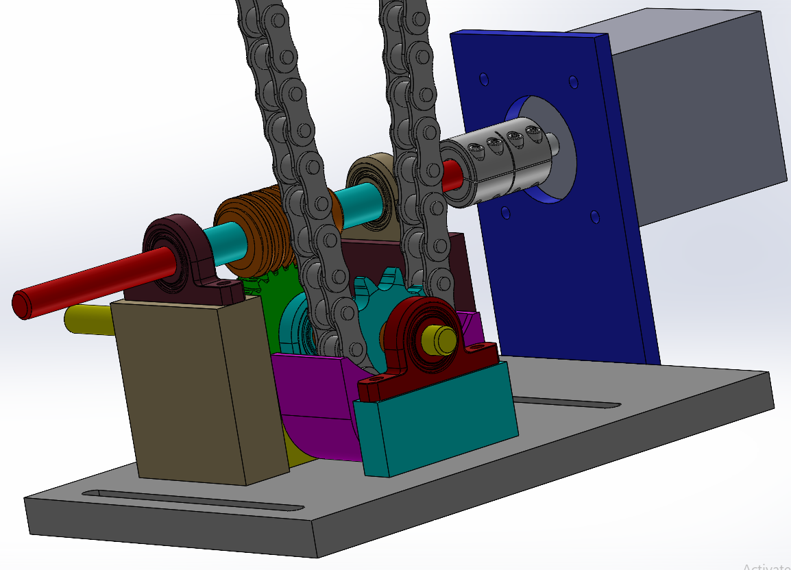
An altered design to allow for much increased torque to rotate the nozzle during operation.
With the worm and accompanying worm gear I picked, thee was a speed ratio of 30. On paper, this meant I had far more control/resolution over the rotation of my nozzle. To clarify this, let's start from the stepper motor and work our way out to the nozzle/large sprocket. The stepper motor takes 400 steps to rotate 360° as in, each step rotated the small sprocket attached to the motor by 0.9°. The small sprocket(made with 10 teeth) was attached via a chain to a larger sprocket(made with 40 teeth). The ratio of teeth also represents the gear ratio; hence, I was working with a gear ratio of 4. Now, it takes 1600(400x4) steps to rotate the small sprocket 360° (0.225°/step). Now, this is where things get a little absurd with the worm/worm gear configuration. Given a speed reduction of 30, it would take 48,000(400*4*30) steps to rotate the nozzle by 360°(0.0075°/step). Once again, this is on paper. Realistically, the chain isn't always in tension, there's a little bit of backlash, and the system isn't perfectly rigid! However, this will be more than enough to run my experiments and collect some really cool data!
As nifty as it was to build this system; if I was really going to rotate this pipe and collect data while a supersonic jet was blasting out the end, I needed a way to make sure my nozzle was rotating as much as I was telling it to. The solution to that problem was to install a rotary encoder. The good news was that this is a relatively inexpensive device that was very accurate. The not so good news was that I had to figure out how the heck to mount this encoder onto an already designed assembly, integrate a new device into my system, and program it all to work together. After some soul searching, the fastest thing I could do was 3D print something I could slot into my build! Take a look below.
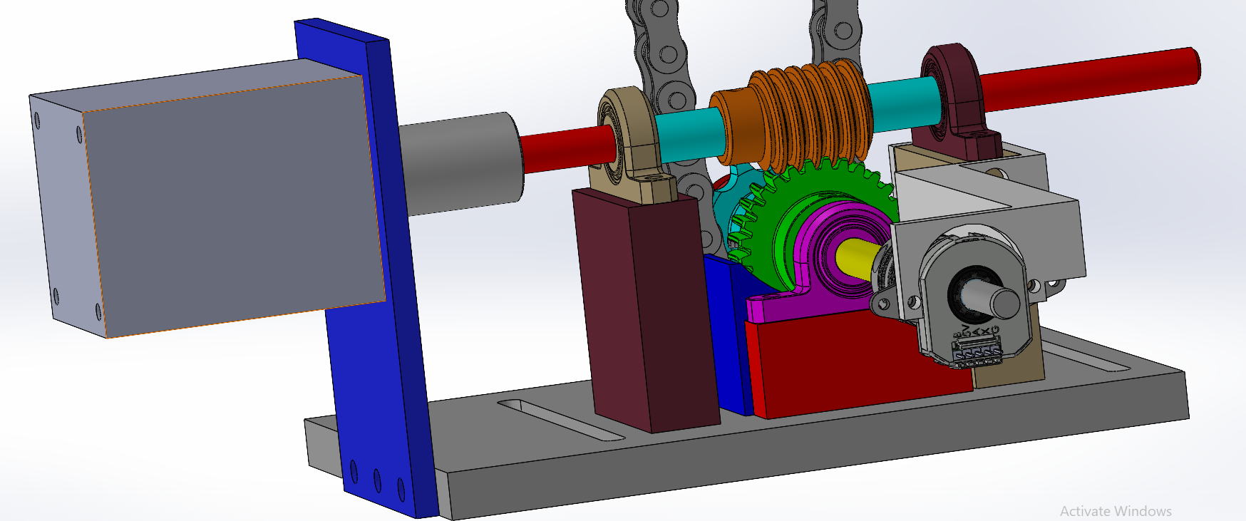
An altered design to allow for much increased torque to rotate the nozzle during operation.
With my upgrades in place, I could take high resolution acoustic measurements across various azimuthal planes! To try and keep things reasonable, I selected my increment in degrees to be 1.8°. That way, it would take 201 measurements to characterize the acoustics throughout the entire (360°) azimuthal plane! Now that I have a functional system, the next stop would be measurements and, finally, data visualization. In this next image, you can take a quick look at the results!
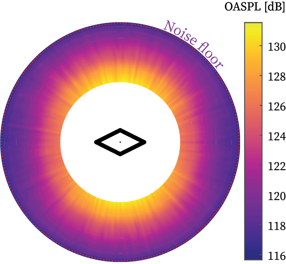
Global view of acoustics generated by a Mach 2 diamond-shaped jet at a pressure ratio of about 8 atmospheres.
To give you a better perspective of what we're looking at, here's another image presenting the acoustic surface/map on top of a regular cartesian coordinate system.
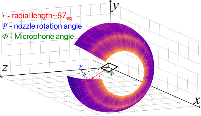
Reconstructed acoustic surface mapped on top of a Cartesian coordinate plane.
With that in mind, let's take a look at the three-dimensional acoustics of the jet from a different perspective. This time we have more of an isometric view of it.
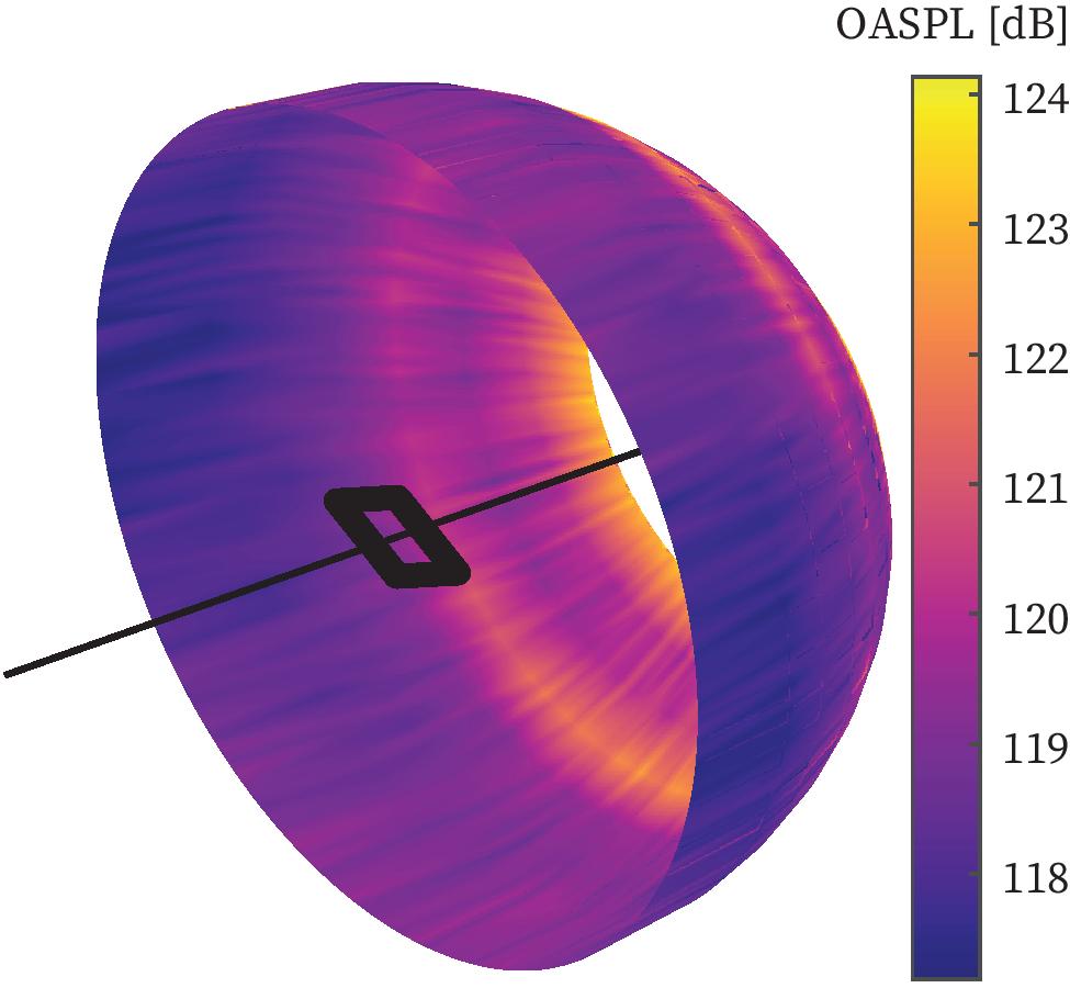
Acoustic surface reconstruction at NPR =4.3 (screech). Nozzle exit outline is not to scale.
One of the magical things about high resolution microphones measurements is the ability to resolve the frequency of the acoustic waves observed! Using Project Y, I could take a look at the frequency content in an entire azimuthal plane! While the image above represents more of a global overview of the acoustics generated by this nozzle, the following image will tell you the frequency and amplitude of the acoustics radiated toward one particular microphone. In particular, the microphone sitting at the sideline!
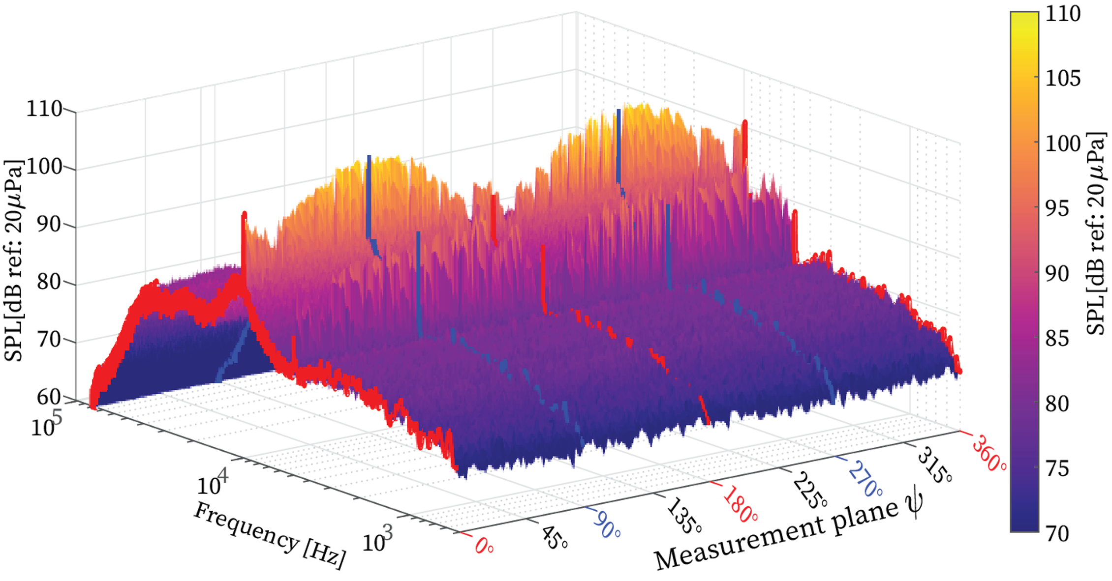
Spectral content of noise captured by microphone at 90° relative to the jet exit axis.
I've taken to explaining the frequency spectral features in terms of geographic features since it’s a touch more intuitive. Let’s start from the low frequency content where you traverse the great plains of turbulent mixing noise. This progresses into sheer cliff screech tones. Beyond the fall-off, you see the mountainous build of BBSAN with harmonic tones forming the secondary peaks of this spectra.
I had the opportunity to present some of this work at the 2023 AIAA Aviation conference in San Diego! Part of the conference is submitting an academic article to supplement our presentations, so I've attached a copy of the manuscript here! Click on this text to take a quick peek at it .
There's the story of Project Y and where it stands so far. I've left out a lot of the nitty-gritty stuff but I think I've gotten a good chunk of story out. I also managed to develop my 3D model quite a bit and integrate a full-scale model of the anechoic chamber that I use. Click here to view an interactive full-scale 3D model of the hardware discussed here and click here to check out how that was integrated into the anechoic chamber environment. This is a pretty large file so it may take a while to load.