What is a non-axisymmetric nozzle?
To make it as straightforward as possible, let's consider a non-axisymmetric nozzle to be one that is NOT circular at the exit. Why does that matter? Well, the geometry of a nozzle actually dictates a lot of what that nozzle is capable of doing! In the world of supersonic jets, the circular nozzle reigns supereme for a couple of reasons, but I'll just mention two of them: 1. Circular nozzles give you lower frictional thrust losses since they tend to have higher area-to-perimeter ratios. 2. They're easy(ish) to manufacture! Almost a century ago, deriving curvature of the diverging portion of a Converging-Diverging (essential for flow to go supersonic) nozzle was defined using the Method of Characteristics (i.e. MoC nozzles) to eliminate the production of waves within the nozzle. This would lead to a waveless supersonic flow at the nozzle exit at ideal conditions (static pressure of the jet matches ambient). This process was automated so you could easily scale the size of your nozzle.
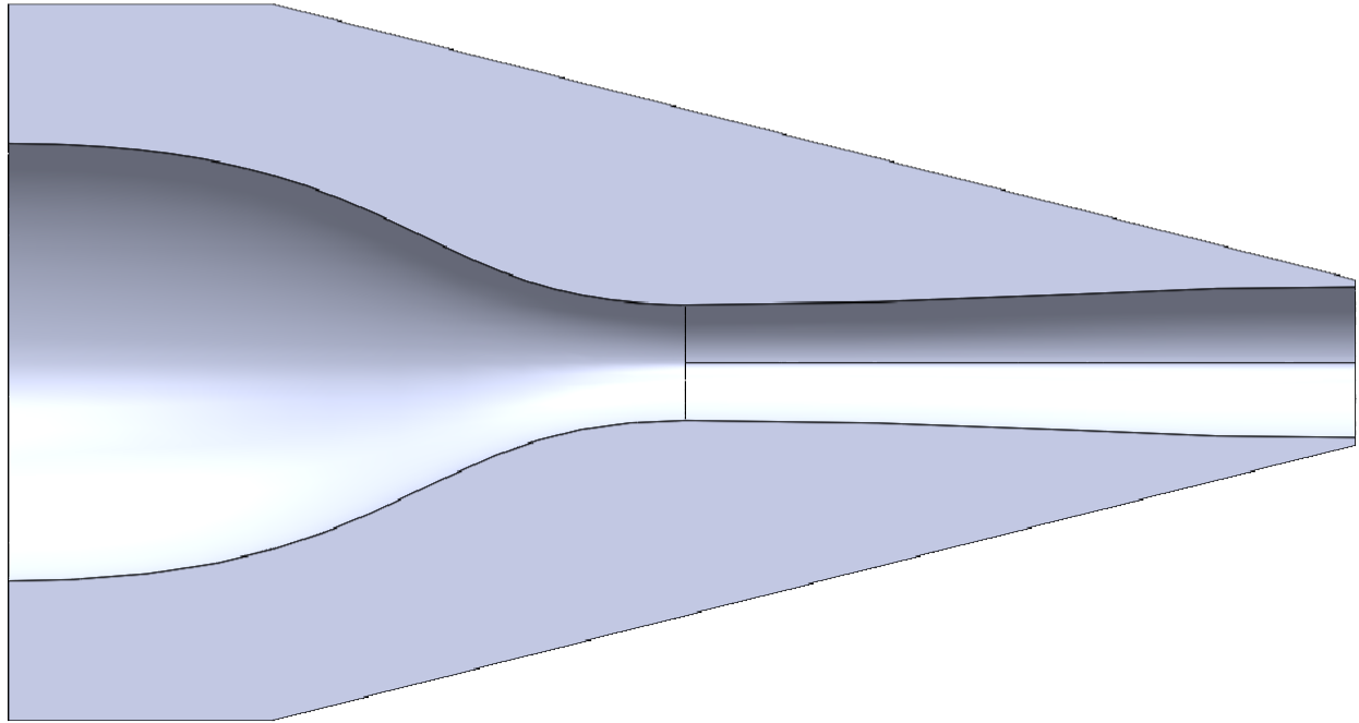
Slice of nozzle illustrating converging portion and MoC designed diverging section .
This method would generate a 2D line. However if you wanted a circular nozzle, all you had to do was rotate that line about some predefined centerline! For rectangular nozzles, this was a little more tricky. Most designers opt to have straight sides on the shorter sides and a curvature that follows the Method of Characteristics on the longer sides. Outside of these canonical geometries, the rules tend to get a little more...wild. For instance, there is no well-defined rules or structure to defining an elliptic or diamond nozzle. As a result, the design of these nozzle geometries is left up to the designer.
The majority of my doctoral degree journey has been sppent studying the diamond nozzle. The diverging portion of this nozzle was designed such that it had some constant rate of expansion. No method of characteristics here! In the final portion of my studies, I also made a rectangular nozzle and an elliptic one. This was a huge learning process for me from mock-ups, to tolerances, through machinability, design, and manufacture! I'll try to talk about the design of each one here.
The goal here was to design a Rectangular nozzle. It would have the same overall length as the diamond nozzle and also be designed for Mach 2 flow at the exit. The extra wonky part of this design was that the nozzle had to be split in two! This was done for the sake of machinability. It's really freaking hard to insert tools deep inside a block of solid metal and carve out an interior geometry with a smooth finish and curves that fit the orginal MoC design. Splitting the beast in two would allow for the precise machining required to manufacture the piece. The drawback was that I also had to figure out how to mate the two pieces together. The best solution here would be to insert a bunch of bolts as well as a sealant/gasket to hold things together. The first step here was to design an inlet that would converge from a circular pipe to rectangular throat. This process involved generating 6th order equation driven curves to ensure that the transitions occurs smoothly over the length of the nozzle that we designated to the converging portion. Below, you can see a visualization of the inlet-to-throat portion of a rectangular nozzle.
Schematic diagram of circular inlet to rectangular throat.
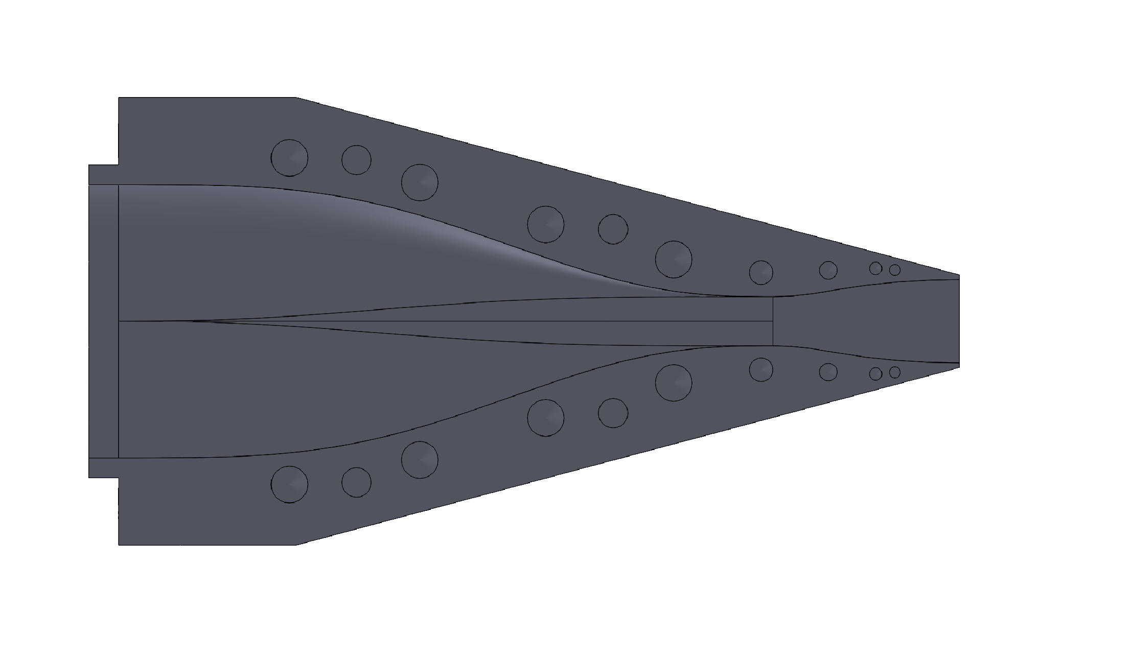
After establishing a subsonic portion, it's time to move onto the supersonic portion of the nozzle. Due to the complexity of the interior geometry, it's exceedingly difficult to manufacture this piece out of a solid block of metal. As a compromise, common for larger-scale nozzles & wind tunnels, the nozzle is manufactured in two pieces. That's why there are bolt holes in the image above and in the final design of my rectangular nozzle below!
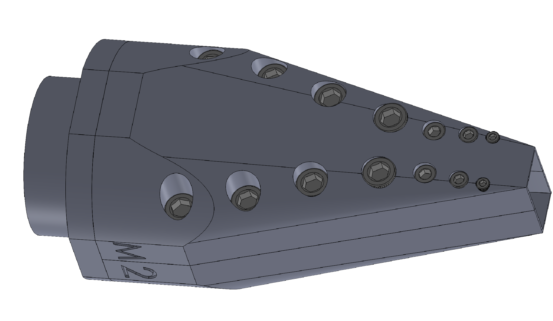
Complete design of Mach 2 Rectangular nozzle of aspect ratio 2.
Overall this leads to a sweet looking rectangular nozzle. you can click on this link to take a closer look at the design!
Elliptic nozzle
Another geometry that has seen quite a bit of action, is the elliptical one. Designing the supersonic portion of this nozzle is a little more tricky. Supersonic rectangular nozzles tend to see quite a bit of action in the form of wind tunnels. As a result, there is a knowledge base to build off of. Meanwhile, the elliptical nozzle does not have a strong application for testing/manufacturing. Hence, there is no clear cut design principle to forming the supersonic portion. After a lot of discussion and testing, we decided to use multiple MoC lines between the throat and exit plane. We ended up with 20 lines spaced between the minor and major axis of the ellipse. These lines would act as "guidelines" for the modeling software to use when forming the surface. You can see our visualization of the supersonic portion here!
A MATLAB visualization to indicate the various MoC lines created to dictate the geometry of the elliptic nozzle.
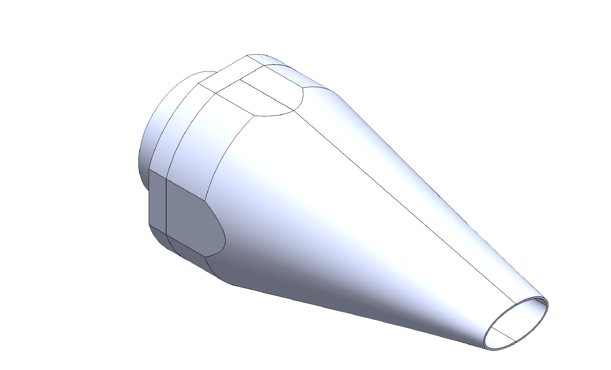
The final step in the process would be to finish out modeling the nozzle as I did earlier with the rectangular one. The final design of the nozzle can be seen below.
Completed nozzle design.
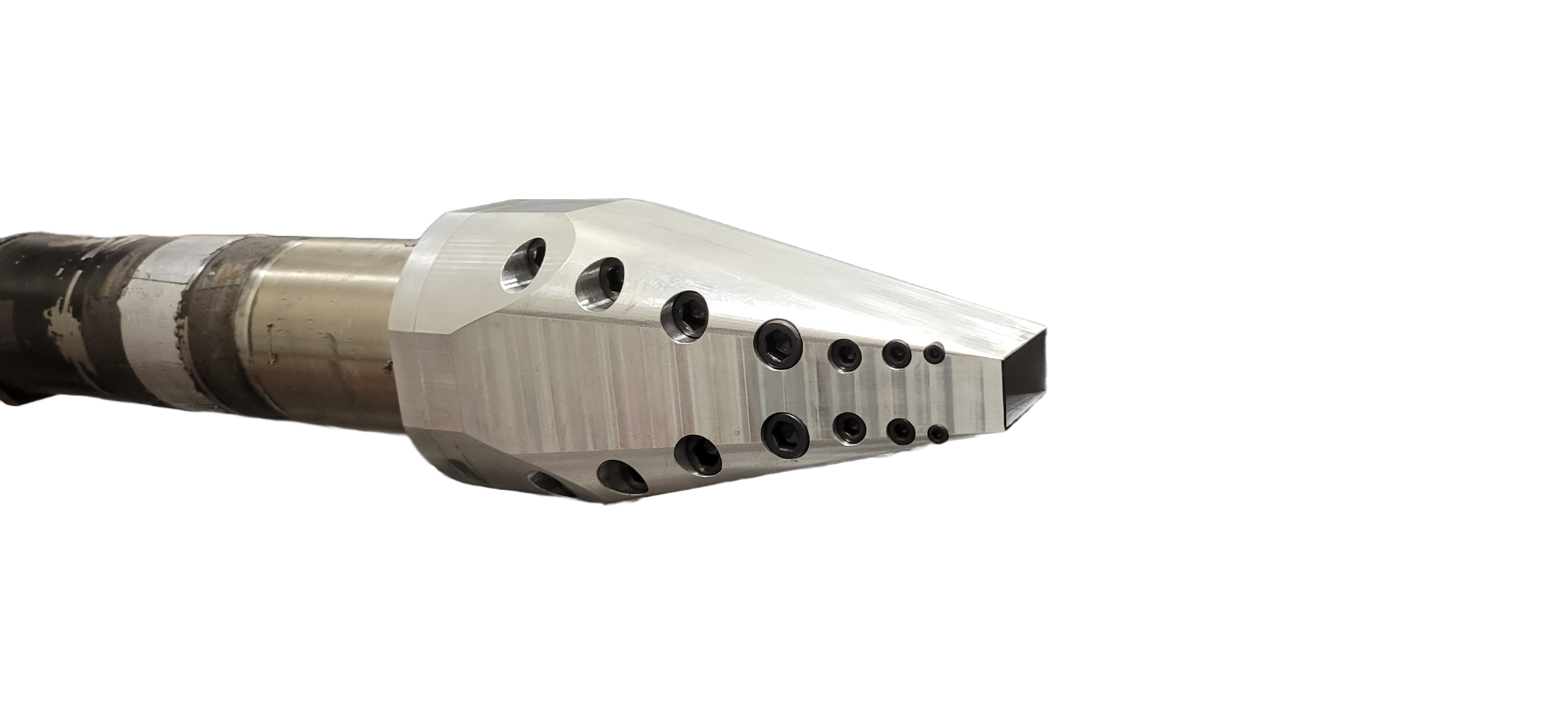
Alternatively, you can click here to take a peak at the model. The elliptic nozzle still needs to have bolt holes assigned to it before it is ready to be manufactured and it will be uploaded here when it is complete. For now, an image of the assembled rectangular nozzle attached to a jet facility.
Assembled rectangular nozzle in jet facility.

